


 ™
™


Thermal Debinding and Sintering 101
Introduction
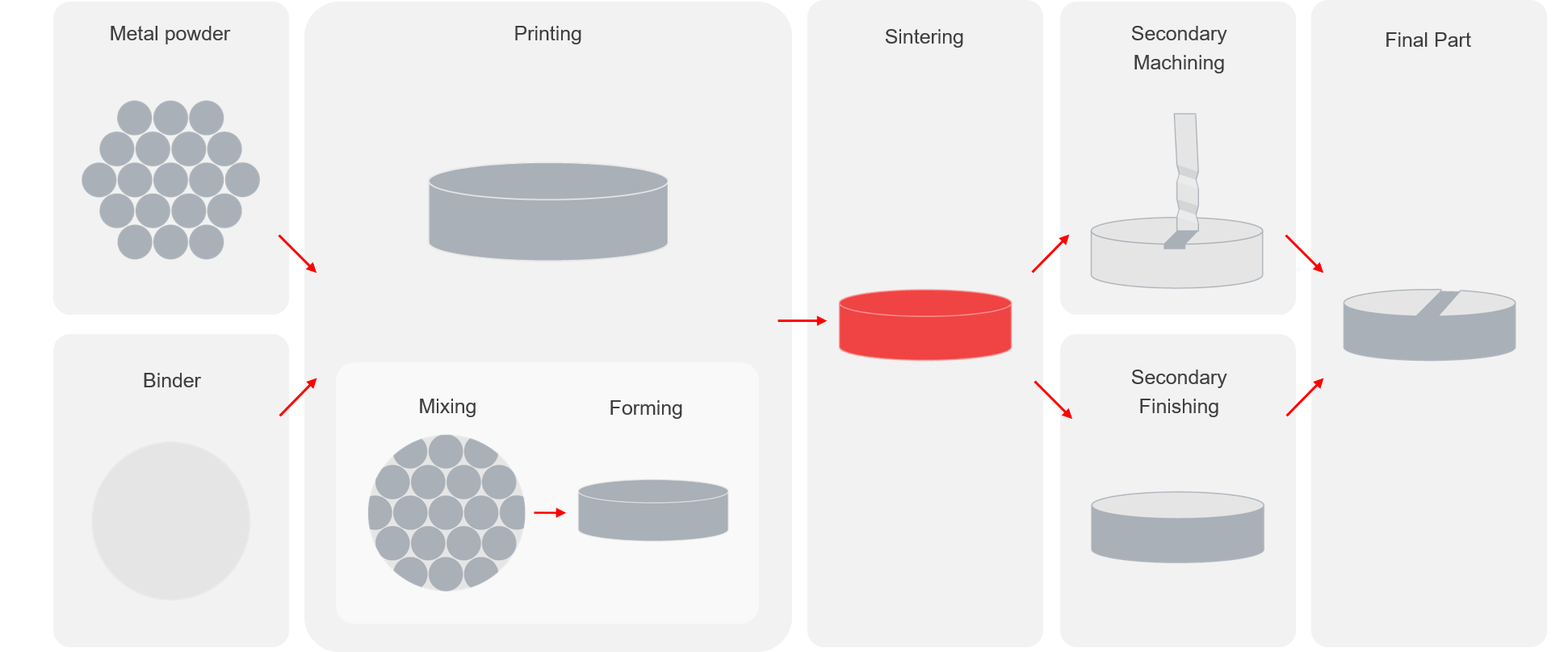
Sintering is the final step of all powder metallurgy processes, including the metal 3D printers at Desktop Metal. During sintering, brown parts (a combination of metal powder and binder) are first heated to a temperature where the binder evolves and is removed from the parts. The furnace then ramps up to the sintering temperature of the metal which is just below the melting temperature of the material, fusing together the metal particles. After sintering is complete there is little or no evidence of the original powder particles, fabrication process and parts have very low porosity.
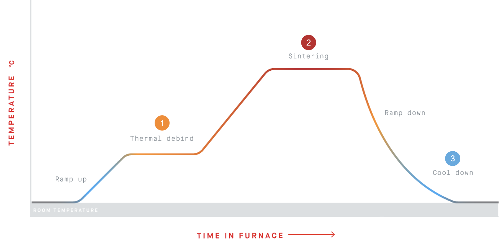
3 Main Steps
_1 Binder is removed
Either by degradation (chemical interaction with furnace gas) and/or evaporation (vaporized binder)
_2 Metal particles fuse
Densification and pore removal occurs as metal particles migrate and fuse
_3 Furnace cools down
Furnace cools so parts can be safely removed
Binder Removal
The first step in the sintering cycle is to remove the binder from the part. Depending on the specific binder being used, this is done via degradation and/or evaporation.
_Degradation: A chemical reaction between the gas used in the furnace and the binder that degrades the binder into new components that can then be evaporated.
_Evaporation: Binder is brought to an elevated temperature where it becomes vapor. Many times, the binder will break into small molecules before evaporating. The vapors can then leave the part through surface-connected pores that will later be removed during sintering. Gas flow helps to sweep the binder away from the part and out of the furnace chamber.
The temperature at which thermal debinding occurs depends on both the binder material and metal being used, but generally happens between 200C and 550C. Furnaces typically ramp up slowly to ensure the binder isn’t converted to gas too quickly, potentially damaging parts.
During the furnace cycle, gas constantly flows through the furnace to remove binder and ensure the atmosphere prevents oxidation of the metal. The gas will either be inert or reducing to ensure minimal oxidation occurs.
Purging
After the thermal debinding is complete, the furnace can be purged with either an inert gas or by pumping down to a low pressure to ensure all binder has been removed from the furnace environment and the furnace atmosphere is inert (clean) before beginning a ramp in temperature to sintering temperature.
Sintering
Sintering is the process of densification, where diffusion of particle surfaces take place and metal parts begin to bind together, closing off the voids where the binder material previously was. The part shrinks between 15-20% (linearly). There are 3 main stages of sintering: presintering, intermediate sintering, and final sintering.
_Presintering
During pre sintering, necks begin to form between powder particles, mass transport occurs from the near neck region to the neck region. In steels, this occurs between 600° and 900° C. During pre sintering there is little to no shrinkage.


_Intermediate Stage Sintering
During intermediate sintering the necks continue to grow while the pores shrink, eventually becoming round. Densification occurs, and by the end of the intermediate stage, parts are generally approximately 92% dense.


_Final Stage Sintering
During the final stage of sintering, pores continue to shrink, and the part further densifies. To optimize part density, sintering temperatures and holds are closely monitored to control and avoid grain growth, which can occur if parts are left at elevated temperatures.


Cooling
Cooling is not as simple as just turning off the heating elements. Generally, the furnace will be backfilled to near-atmospheric pressure with an inert gas to help with cooling while maintaining an inert atmosphere.
The result
The result of sintering is a dense, polymer-free metal. The metal has no evidence of its manufacturing method - either printing or molding - and is isotropic, showing the same properties in all directions. As shown in the micrograph below, the powdered metal origins have been erased, and the grains of metal have grown larger than the original powder particles. Desktop Metal printed parts meet or exceed material standards from American Society for Testing and Materials (ASTM) and Metal Powder Industries Federation (MPIF). The homogeneous microstructure of sintered parts makes them extremely attractive for many different applications.
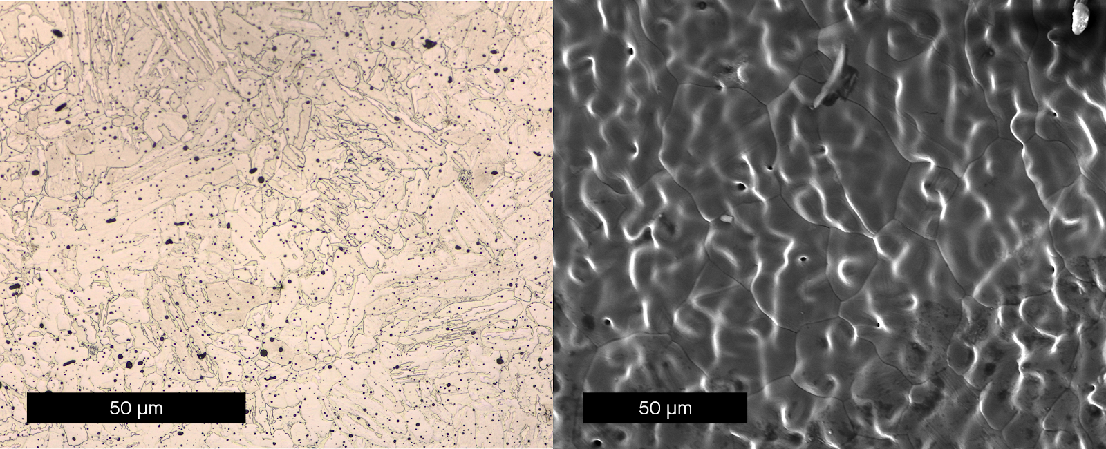
Shown here are a polished micrograph of the cross section (left) and surface (right) of a 4140 steel sintered part.
Desktop Metal Sintering Solutions
Desktop Metal’s mission is to make metal 3D printing accessible to all engineers and manufacturers. To do it, Desktop Metal provides complete solutions for metal additive manufacturing, including a furnace.
The Desktop Metal furnace is designed to be the easiest to use sintering furnace ever made, allowing users to achieve the highest material properties and densities possible with ease. Desktop Metal furnaces have a peak temperature of 1400°C, allowing for the sintering of a wide variety of materials. Parts are loaded into a graphite retort, which helps to ensure uniform gas flow and heating during the entire sintering process. This ensures that the binder is efficiently removed and parts are in a clean, inert environment.
To further ensure parts are uniformly heated throughout the sinter cycle, precisely-controlled heating elements surround the retort on four sides. Both the Studio and Shop furnace also pull vacuum throughout the entire sinter cycle allowing for very low levels of gas usage during the cycle.
With a large, fully-accessible sinter volume, the Desktop Metal Shop and Studio furnaces are the most accessible way to batch sinter metal parts.
3rd Party Sintering Solutions
To complement the powder metal manufacturing industry, furnace companies have been producing sintering furnaces for the MIM and press and sinter industry. These furnaces often feature large sinter volumes and are capable of using gases, such as Hydrogen, which can be beneficial for reducing oxides within the part. These furnaces can also have reduced cycle times due to more expensive heating elements, all-metal retort material, and faster cooling cycles via water-cooled vessels and furnaces with built-in fans or blowers to accelerate cooling.
For some extremely high-volume applications, a continuous furnace - a conveyor belt running through different hot zones to run the entire sinter cycle in a continuous process - may also be used. These furnaces can be paired with automation to immediately remove a part from a mold or press and place onto the conveyor belt. These furnaces are extremely large, often over 100ft long, and are extremely expensive. These furnaces are not flexible when it comes to changes in cycle times to incorporate different materials or cycles.
Sintering Simulation
For many, sintering still remains somewhat of a black box, with little understanding of what actually happens to the parts throughout the cycle. During the furnace cycle, parts experience significant forces caused by gravity, friction, and uneven shrinkage due to density variations. This may lead to deformation, opening the door for potential warping, cracking, slumping, and parts that emerge from the furnace out of tolerance.
Currently, many manufacturers must rely on best practices and the intuition of a relatively few engineers who have hands-on experience with sintering to ensure part success. Though large organizations specialized in powder metallurgy are able to optimize geometry and design custom ceramic setters to hone their sintering processes, this still involves multiple tries and some guesswork.
As the number of first-time sintering users continues to grow, thanks to increasing availability of affordable additive manufacturing processes like the Desktop Metal Studio System and Shop System, this guesswork must be eliminated to enable broader adoption.
Live Sinter
A first-of-its-kind software application, Live Sinter’s speed and ease of use help make sintering more manageable for all users. The software is capable of simulating the complex deformation and compounding forces parts experience during sintering and generates adjusted geometry for printing based on that simulation.
Live Sinter achieves this by first modeling the sintering behavior of bound metal powder. The software then simulates the shrinkage and distortion expected to take place in the furnace. Using that information, the software runs a series of iterative simulations to automatically generate a “negative offset” geometry to compensate for the distortion. That new geometry is sent to print and when sintered, results in a straight, defect-free part out of the furnace.
Printed Negative Offset
Sintered Straight