


 ™
™


Live Sinter
Sintering challenges
One of the main challenges to the broad adoption of MIM-based metal additive manufacturing technologies is sintering. Sintering has existed for thousands of years, since the first ceramic pots were sintered, but only began being used for metal manufacturing in the first half of the 20th century. Though it is used in metal injection molding, pressed and sintered, and now additive manufacturing to fabricate millions of parts each year, the sintering process is still somewhat of a black box.
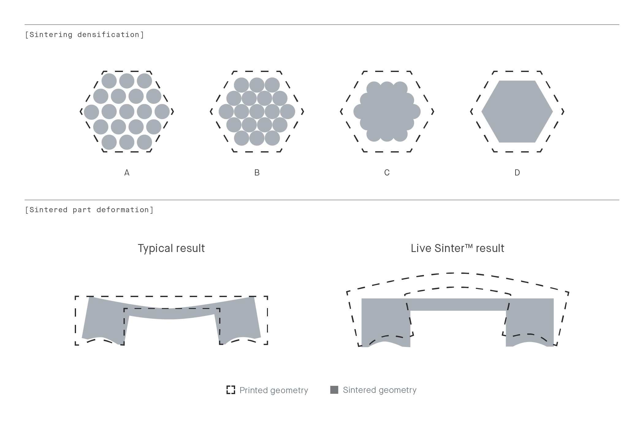
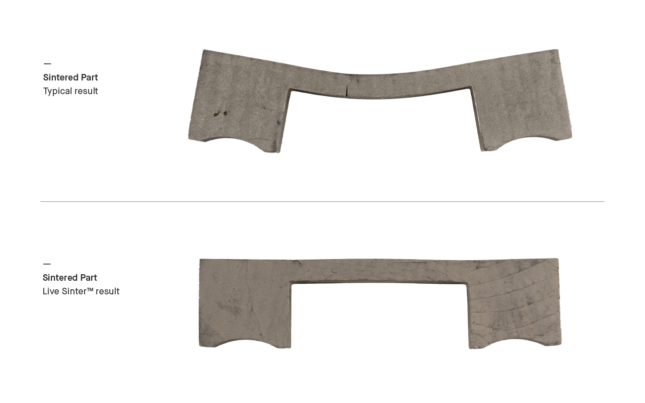
During sintering, brown parts (a combination of metal powder and binder) are heated to just below the metal’s melting temperature. First, the binder evaporates from the part, this is followed by mass transfer through viscous flow, plastic flow, condensation, and diffusion where metal particles fuse together, resulting in a dense metal part that has shrunk by around 15 percent. During this process, the part experiences significant forces caused by gravity, friction, and uneven shrinkage due to density variations, and this may lead to deformation; opening the door for potential warping, cracking, slumping, and parts that emerge from the furnace out of tolerance. Currently, manufacturers must rely on best practices and the intuition of a relatively few engineers who have hands-on experience with sintering to ensure their parts emerge from the furnace successfully.
Though large organizations specialized in powder metallurgy are able to optimize geometry and design custom ceramic setters to hone their sintering processes, this still involves multiple tries and some guesswork. As many first-time sintering users emerge thanks to increasing availability of affordable additive manufacturing processes like the Desktop Metal Studio System and Shop System, this guesswork must be eliminated to enable broader adoption. Unlike larger organizations, these new users lack the experience, time, and resources to successfully modify designs and processing parameters for each job. As a result, these new users are helping drive the need for sintering simulation tools that can make sintering technologies more understandable, repeatable and widely adoptable.
The Solution
Live Sinter is a first-of-its-kind software, delivering both speed and ease to the sintering process. The software is capable of simulating the complex deformation and compounding forces that a part will experience during sintering, and in just minutes generate adjusted part geometry for printing.
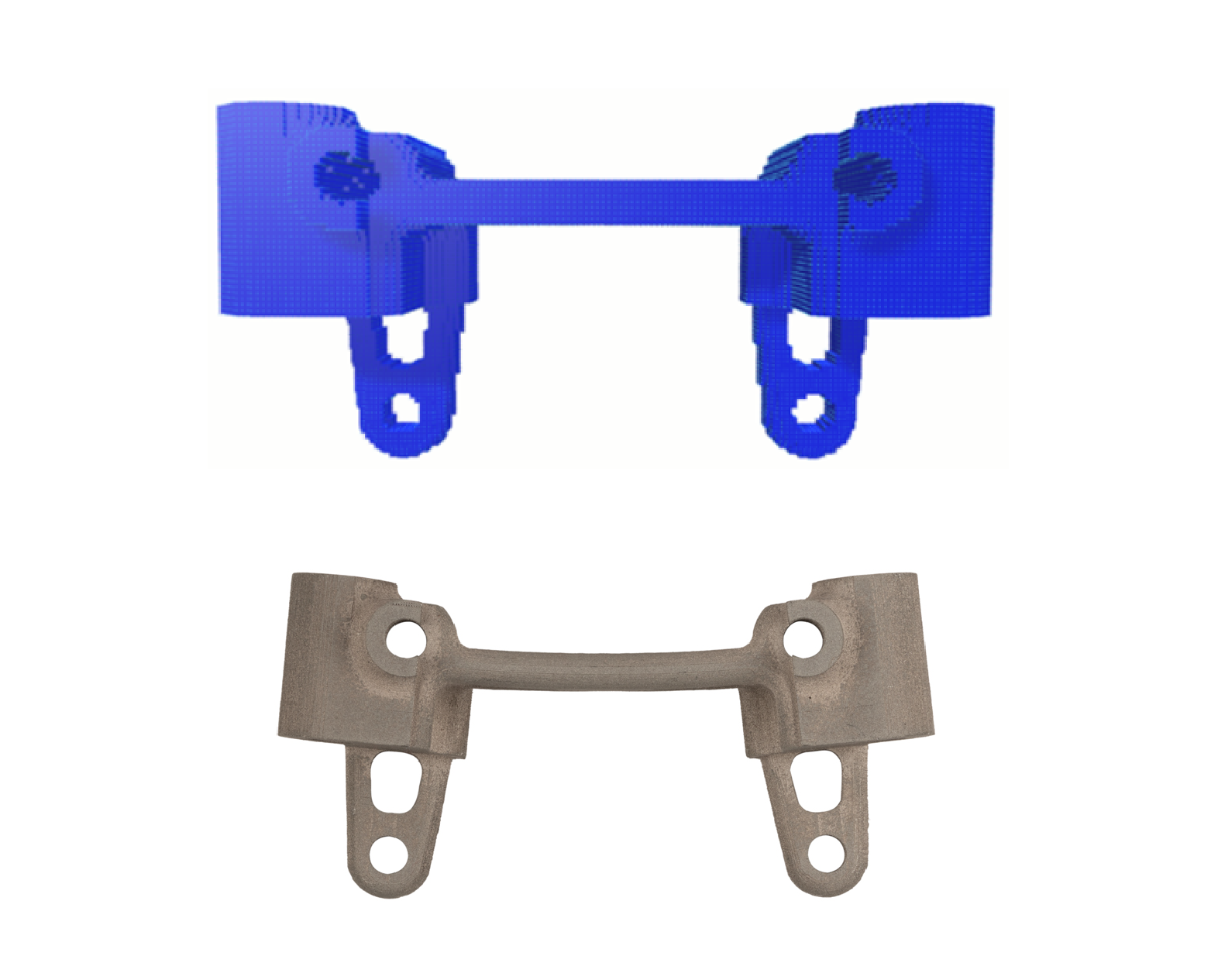
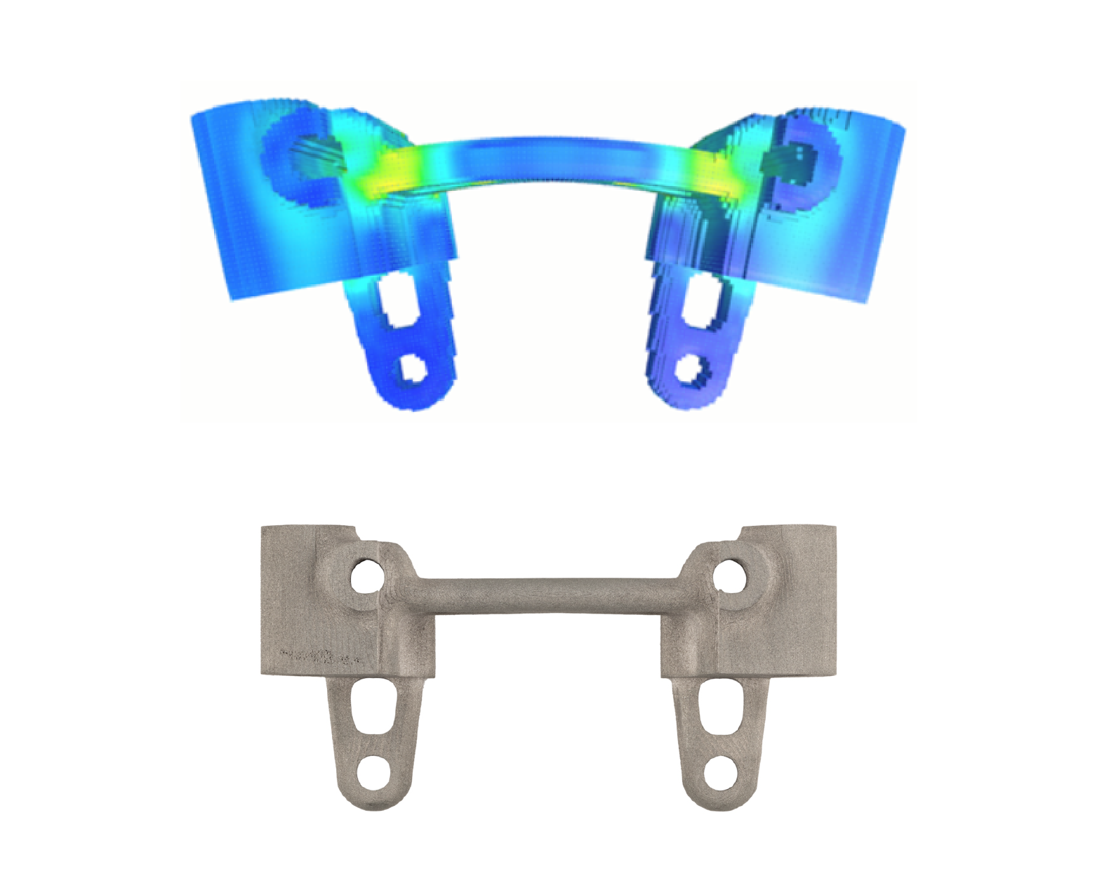
Live Sinter achieves this by first modeling the sintering behavior of bound metal powder. The software then simulates the shrinkage and distortion expected to take place in the furnace. Using that information, the software runs a series of iterative simulations to automatically generate a “negative offset” geometry to compensate for the distortion. This “negative offset” geometry is sent to print and when sintered, results in a straight, defect-free part out of the furnace.
How it works
Developed over a year in collaboration with Desktop Metal’s world-class material science team, Live Sinter works by using an iterative simulation operation. The best way to understand this process is through a simple example.
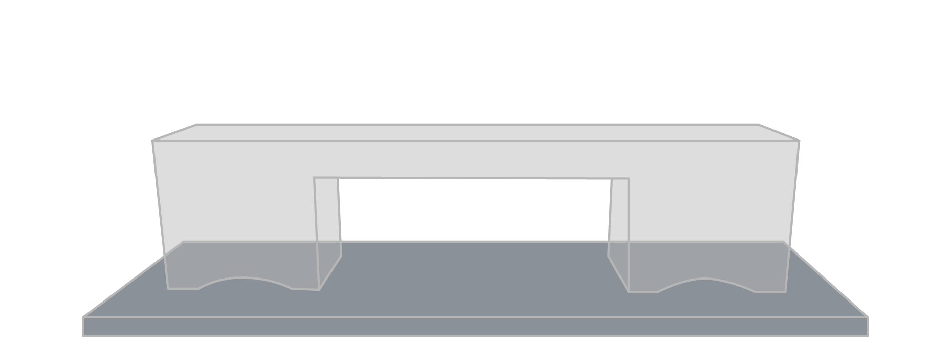
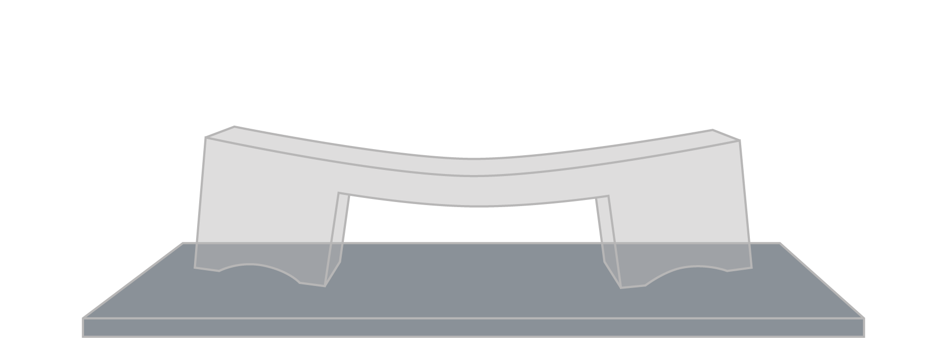
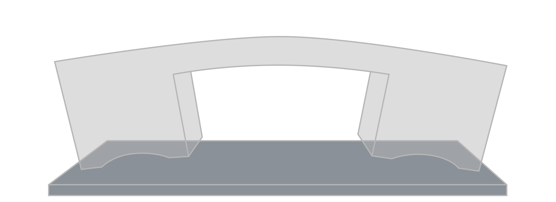
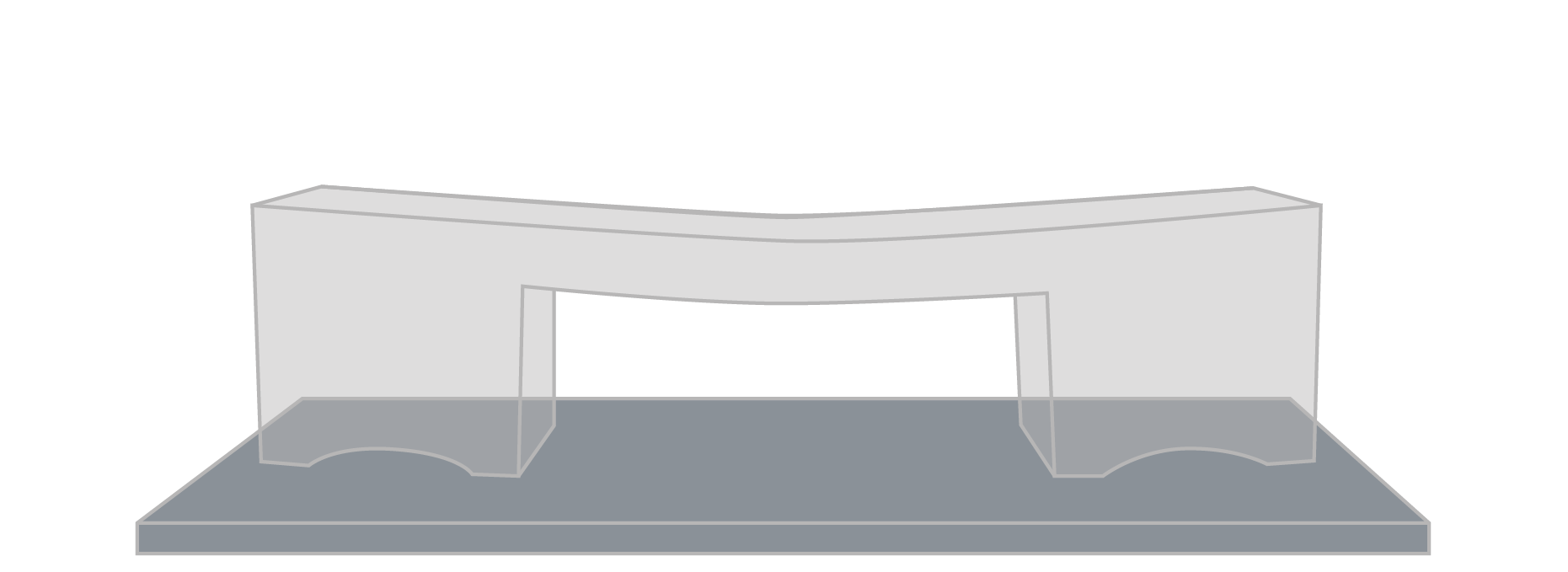
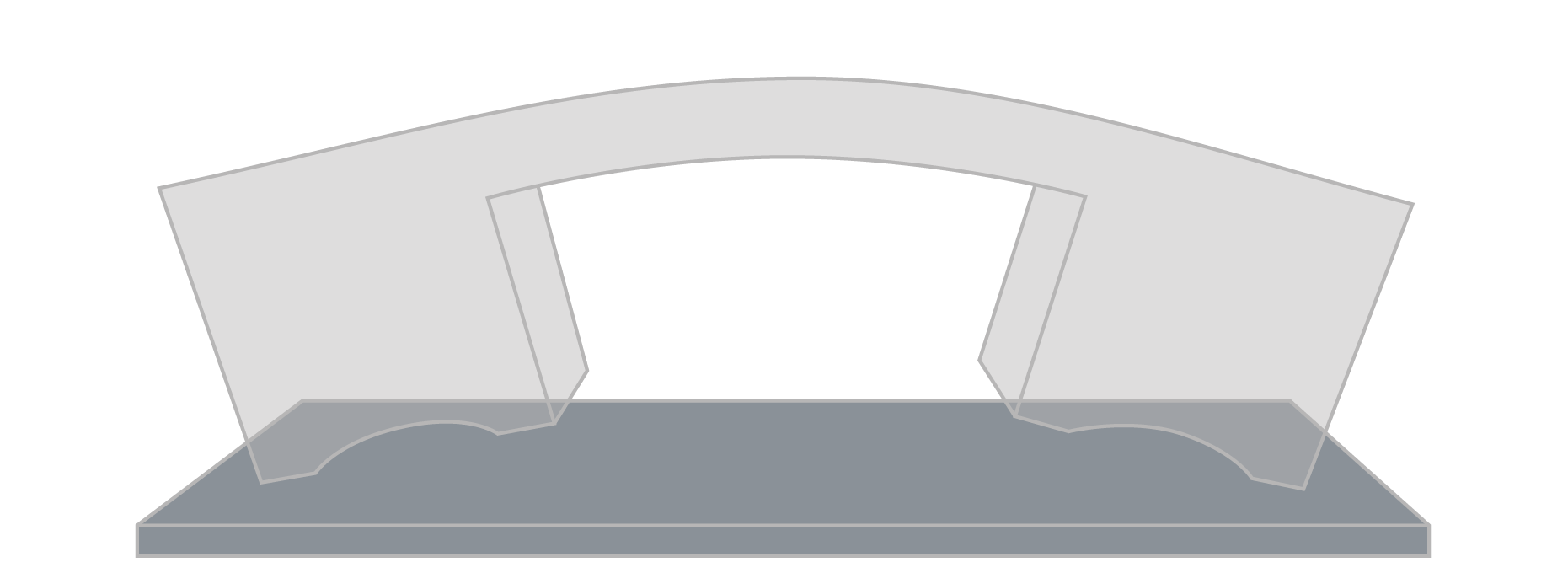
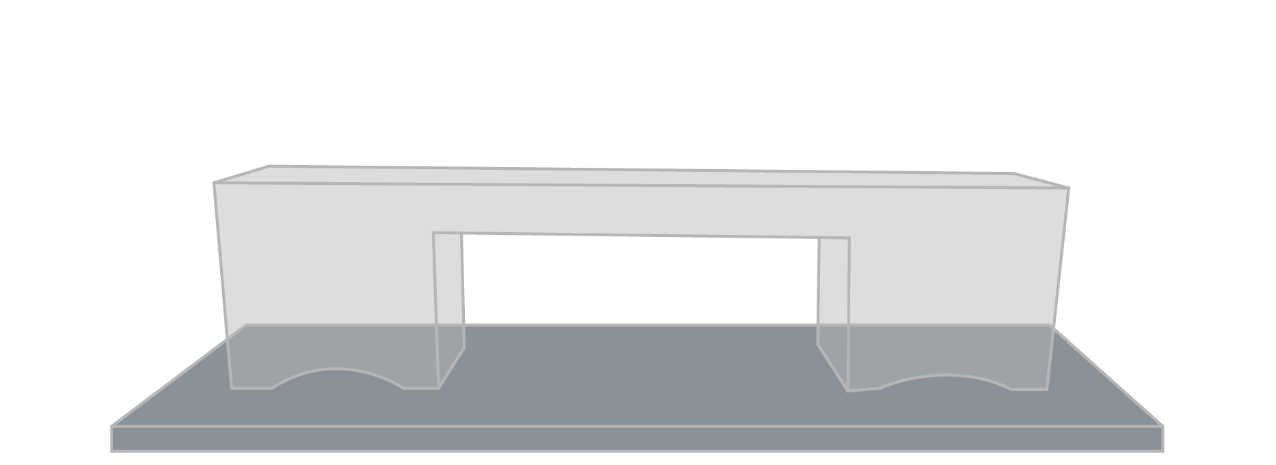
This process of simulating sintering and generating negative offsets is iterated until the simulation result matches the intended final geometry.
Producing the negative offset is not as simple as simply inverting the deformation that occurs during sintering because there are a host of factors at work during sintering that affect the final part outcome, and they all must be taken into account when creating the negative offset. Each new iteration is an entirely new physics problem that must be solved to generate the next iteration of the negative offset.
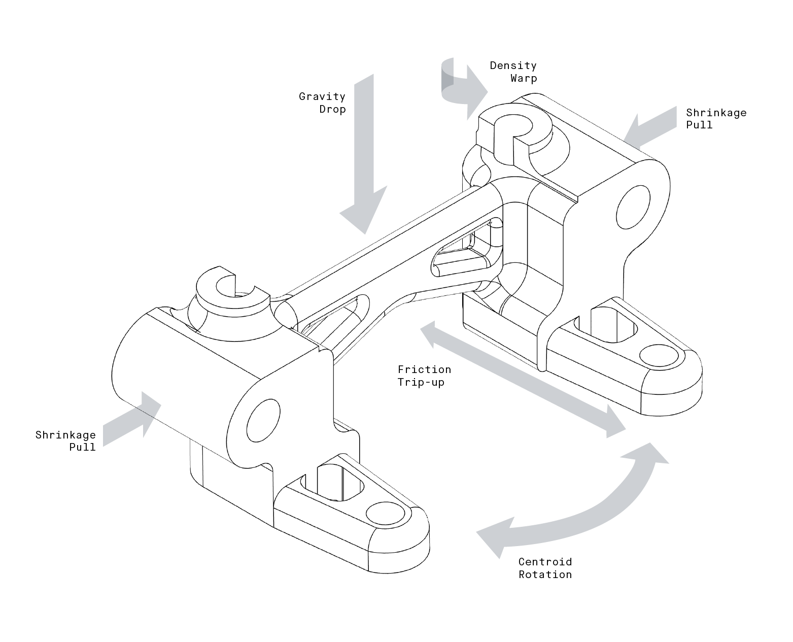
A few parameters that must be taken into account during the physics simulation are:
- Gravity Drop: Elastic and plastic motion downwards
- Shrinkage Pull: Multi-directional contraction
- Friction Trip Up: Stationary regions getting stuck against setters
- Centroid Rotation: Uneven weight distribution bending
- Density Warp: Varying shrinkage due to powder packing variations
Better Parts
In addition to generating parts with more reliable dimensional accuracy, Live Sinter also renders parts of higher quality. Typically, a part during sintering experiences tension and various other forces during densification when particles resist mass transport within the part. This tension results in a greater likelihood of cracking and internal fractures. By contrast, geometries generated by Live Sinter are printed intentionally to aid the transformation that occurs during sintering, instead placing the part in a state of compression while it shrinks, reducing the chance of cracking.
In the absence of this type of simulation technology, many powder-metal manufacturers rely on static sintering supports to control shrinkage. The use of sintering supports, while effective in controlling a part’s deformation, also constrain the part from achieving its naturally-desired shape, resulting in a higher concentration of stress points. With Live Sinter, parts and supports are both printed with negative offsets, allowing them to shrink in unison without constraint. The result is reduced stress concentration within parts.
As metal additive manufacturing continues to grow in the coming years, so too will the need for sintering simulation. By making the sintering process more understandable and repeatable, Live Sinter gives users unprecedented control over the geometry of their final, sintered parts, and helps to fulfill Desktop Metal’s mission to make 3D printing accessible to all manufacturers and engineers.